GPS data (NMEA sentences and PPS sync pulse) over optic fiber
Last update 27 March 2020 - under construction
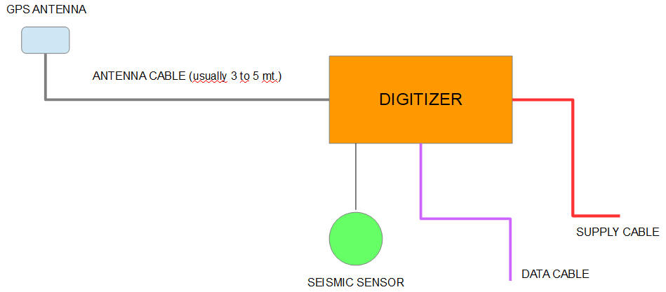
In seismic stations we usually install digitizers taking time from internal
GPS receiver through external GPS antenna.
GPS antenna is usially placed some meters away from digitizer, cable could be 3
to 5 meters (usually) but sometimes it can be longer when using low-loss RF
cable.
When installing free-field seismic station we have not much problems due to GPS
cable length but what about installing seismic station deep into mining
compound?
Layout of generic seismic installation
Sometimes we can place seismic instruments not so far away from tunnel entry
(such AGOR seismic station) and we can use a long low-loss RF cable to connect
extarnal GPS antenna as just said above, but what about deeper seismic stations
such PRED or CLUD?
Do you really mean you can place 600 meters cable?? Obviously not!
Here you have two options:
GPS signal repeater
There are several models you can find on the market, the ones you can find for this applications are usually expensive (if I correctly remember about 10'000$).
External GPS input
If you are planning to install seismic stations into mining systems or caves you can plan to buy digitizers with external timing input, here some examples:
In this case there is an external GPS receiver placed outside installation
sending timing data (NMEA sentences and PPS sync pulse) through serial line.
NMEA serial data is sent using serial protocol (usually 4800-8-N-1), usually
RS-232 protocol (on Q330 you can select to work with RS-232 or RS-485 protocol).
There is an additional line for PPS sync pulse.

Timing using external GPS as timing source
In this solution you can send data through cable or optic fiber (using
specific adapters).
On the market you can find GPS receivers with RS-232, RS-485 or TTL output data.
Q330 models supplied with external GPS connector can work as receivers (receive
GPS timing for external device) or as clock source (Q330 can output timing data
for a second Q330).
Digitizers usually work with these NMEA strings (some used for timing, some
used for satellites report):
- GPGGA (fix status)
- GPGSV (data about visible satellites)
- GPGSA (number of active satellites)
- GPZDA (UTC timing)
Output example of NMEA sentences used for timing on digitizer Quanterra Q330
On first installations we used long copper wires (one for ethernet and one for GPS data) then RS-485 encoder/decoder produced by Sara:

External GPS using RS-485 line
We used this solution in mining complex among mountains (PRED station, about 600 meters deep) and we had several troubles during summer storms so we moved to optic fiber.
To send serial data (4800 bit/s) we don't need superior
performances so we can use cheap optic fiber and cheap optic fiber
drivers/receivers we can found from electronic suppliers.
Our first solution was to use 4-core optic fiber (2 cores for ethernet, 1 core
for NMEA, 1 core for PPS) so we made GPS receiver with optic fiber driver and
relative receiver:

First GPS over optic fiber solution (transmitter)

First GPS over optic fiber solution (receiver)
Encoding GPS signals
We just said we need two GPS signals (NMEA sentences and PPS sync pulse) for digitizer timing, let's take a look:

GPS receiver output signals (TTL level)
As we can see from image above, NMEA serial output and sync pulse are produced at different times so why not encode them to a single signal?

Encoding of NMEA (b) and PPS (a) into single signal (d)
To do this we can work at higher bitrate and use additional microcontroller for signal encoding.

Block diagram for GPS receiver and optic fiber encoder

Block diagram for decoder

GPS receiver with GT-310 module and PIC24 microcontroller

GPS decoder with RS-232 interface
Issues
In this solution we found two issues:
Quanterra Q330, if I correctly remember, works with a Motorola
GPS chipset and Q330 needs specific timings for NMEA output after PPS sync
rising edge, so we can't buy first GPS chipset we can find.
We started using Navman Jupiter 30 chipset, obsolete when starting designing
single wire solution.
So we moved on GT310F GPS receiver: after some months of running without
troubles we started having some problems (digitizer internal time was delayed by
1 second from correct time).
We solved with GPS firmware update but it hasn't been so easy due you need to
remove chipset shield, remove resistor, and so on....
PPS sync edge output from GPS receiver is processed by
microcontroller, so I have some delays among PPS edges (PPS edge from GPS, PPS
edge to LED driver, PPS edge from receiver microcontroller).
This creates little jitter of PPS sync edge to digitizer (don't worry, just
about 10us).

PPS delays introduced by microcontrollers (not in scale)
To solve these issues we select Ublox chipsets (I have never
noticed about bugs on these chipsets about our purposes) and new models have
same footprint of old ones.
To reduce jitter we use PPS sync signal to drive LED bypassing microcontroller.
GPS receiver with signal encoder (3th generation)
For new receiver solution we use GPS chipset NEO-6M for following reasons:
we can find very cheap (about 7$) breakout boards such GY-NEO6MV2, this small board gives us connector with serial output and PPS sync pulse
NEO-6M doesn't have flash memory to permamently store configuration but there is onboard eeprom where we can save settings to be loaded at next boot
chipset doesn't output NMEA data but Ublox binary protocol instead: in this way we can reduce transmission payload
Ublox binary protocol gives us GPS epoch time and data about
leap seconds: frome these we can get UTC time compensated by leap seconds
Just take care there are fake NEO-6M marked chipsets on the web...

GY-NEO6MV2 board

Encoder prototype board
- WEBSITE UNDER CONSTRUCTION -
Decoder (3th generation)
Decoder module receives encoded data (bitrate has been increased
to 57600 bit/s).
It generates PPS pulse output (length is 200ms) and outputs NMEA messages.
NMEA messages are generated by Ublox binary data, output bitrate is set to 4800
bit/s and number of visible satellites is limited to 8 for compatibility with
older receivers.

You can choose to mount MAX232 (for RS-232 output) or MAX3043
(for RS-485 output); actually components for RS-485 output are not soldered.

Decoder layout
On COM connector you can find RS-232 signals:
- pin 1 = PPS
- pin 2 = NMEA output data
- pin 5 = GROUND

On J5 connector you can find TTL (3,3 Volt) output.
This solution allows to provide NMEA output for a second device (such Raspberry
Pi), if no NTP server available for timing:
- pin 1 = NMEA output (3,3V)
- pin 2 = GND

decoder schematics
decoder layout
BOM
PIC24 firmware

Decoder placed in Camdenboss DIN enclosure
BOM:
| Part | Value | Device | Package | Description |
| C1 | 12063C475KAT2A | C-EUC1206K | 1206 | 4,7uF - 25V - 10% X7R |
| C2 | GCM155R71C154KE2D | C-EUC0402 | 0402 | 150nF - 16V - 10% X7R |
| C3 | 12063C475KAT2A | C-EUC1206K | 1206 | 4,7uF - 25V - 10% X7R |
| C4 | 12063C475KAT2A | C-EUC1206 | 1206 | 4,7uF - 25V - 10% X7R |
| C5 | 12063C475KAT2A | C-EUC1206 | 1206 | 4,7uF - 25V - 10% X7R |
| C6 | 885012208030 | C-EUC1206 | 1206 | 100nF - 16V - 10% X7R |
| C7 | 885012208030 | C-EUC1206 | 1206 | 100nF - 16V - 10% X7R |
| C8 | VJ1206A180JXJPBC | C-EUC1206 | 1206 | 18pF - 16V |
| C9 | VJ1206A180JXJPBC | C-EUC1206 | 1206 | 18pF - 16V |
| C10 | EMK316AB7106KL-T | C-EUC1206 | 1206 | 10uF - 16V - 10% X7R |
| C11 | 885012208030 | C-EUC1206 | 1206 | 100nF - 16V - 10% X7R |
| C12 | 885012208030 | C-EUC1206 | 1206 | 100nF - 16V - 10% X7R |
| C13 | 885012208030 | C-EUC1206 | 1206 | 100nF - 16V - 10% X7R |
| C14 | 885012208030 | C-EUC1206 | 1206 | 100nF - 16V - 10% X7R |
| C15 | 885012208030 | C-EUC1206 | 1206 | 100nF - 16V - 10% X7R |
| C16 | 885012208030 | C-EUC1206 | 1206 | 100nF - 16V - 10% X7R |
| C17 | 885012208030 | C-EUC1206 | 1206 | 100nF - 16V - 10% X7R |
| C18 | 885012208030 | C-EUC1206 | 1206 | 100nF - 16V - 10% X7R |
| COM | 618009231121 | F09PCB_2 | F09H_2 | SUB-D female PCB 9 pin |
| D1 | 1.5KE18CA | 1.5KER | DO41-10CA | TVS 18V |
| D2 | PMEG6010 | PMEG6010 | SOD123 | Schottky diode 1A |
| D3 | PMEG6010 | PMEG6010 | SOD123 | Schottky diode 1A |
| F1 | 0ZRR0050FF1E | TE5 | TE5 | PPTC FUSE 1A |
| ICD | 281-695-5 | 281695-5 | AMPMODU HE14 | |
| J1 | 487-848 | DCJ0202T | 487-848 | DC POWER JACK |
| J5 | 280377-1 | AMPMODU_02 | 280377-1 | |
| L1 | RLB0914-151KL | RLB0914 | RLB0914 | 150 uH - 0.8A - 10% |
| LED1 | APTL3216SYCK01 | LEDCHIPLED_1206 | CHIPLED_1206 | Yellow LED |
| LED2 | APTD3216LSYCK | LEDCHIPLED_1206 | CHIPLED_1206 | Green LED |
| Q1 | HCU1000-18X | XTALPCB | HC-49 | 10MHz xtal |
| R1 | RN731ETTP4931D25 | R-EU_R0402 | 0402 | 4.93 kOhm - 1% |
| R2 | CRCW04021K00FKEDC | R-EU_R0402 | 0402 | 1.0 kOhm - 1% |
| R3 | 10k | R-EU_R1206 | 1206 | 10 kOhm - 5% |
| R4 | 100R | R-EU_R1206 | 1206 | 100 Ohm - 5% |
| R5 | 100R | R-EU_R1206 | 1206 | 100 Ohm - 5% |
| R6 | 120R | R-EU_R1206 | 1206 | 120 Ohm - 5% *** |
| R7 | 120R | R-EU_R1206 | 1206 | 120 Ohm - 5% *** |
| R8 | 1k | R-EU_R1206 | 1206 | 1 kOhm - 5% |
| R9 | 100R | R-EU_R1206 | 1206 | 100 Ohm - 5% |
| R10 | 390R | R-EU_R1206 | 1206 | 390 Ohm - 5% |
| R11 | 390R | R-EU_R1206 | 1206 | 390 Ohm - 5% |
| U$1 | CNMB_4/2 | CNMB_4/2 | CNMB_4/2/A | DIN enclosure |
| U1 | LM2841XMK-ADJL | LM2840 | SOT23-6 | DC-DC controller |
| U2 | MCP1700-3302E/TO | MCP1700TO | TO92 | LDO 3.3V |
| U3 | PIC24FJ64GA002 | PIC24FJ64 | SO28W | PIC microcontroller |
| U4 | MAX3232CUE | MAX3232CUE | TSSOP16 | True RS-232 Transceivers 3.0V to 5.5V, Low-Power |
| U5 | MAX3043CUE | MAX3043CUE | TSSOP16 | ±10kV ESD-Protected, Quad 5V RS-485/422 Transmitters |
| U6 | 74AC132D | 74AC132D | SO14 | Quad 2-input NAND schmitt trigger |
| XR1 | HFBR-2412TK | HFBR-2412TK | HFBR-X41X | Fiber optic receiver ST |
Schematics
Firmware
Credits:
Sistema di trasmissione dati GPS su fibra ottica per l'acquisitore Quanterra Q330 - modulo di trasmissione - M.Bertoni
Sistema di trasmissione dati GPS su fibra ottica per l'acquisitore Quanterra Q330 - modulo di ricezione - M.Bertoni
Q330 Application Note rev.4 - Kinemetrics
Operating the Q330HR with External Time Source - Kinemetrics
External GPS documentation - Sara